mikewill53
New member
- Joined
- Nov 25, 2015
- Messages
- 1
Hi,
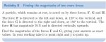
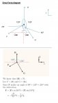
Im a little bit lost on this question thats in my engineering degree. I had a go at drawing the force diagram myself and came up with the top drawing. When I checked againt the universities, they had done it a completley different way. First of all I thought you needed an acute angle which is why i created a line straight down from the centre as opposed to across. As far as I know 210 degrees isnt an acute angle, also if your using 210 degrees how can you have a right angle in the triangle? Obviously theres a reason for doing it like this, Im just wondering what it is and where Ive gone wrong
Regards
Mike