electronic circuit - 2

logistic_guy

Senior Member
Joined
Apr 17, 2024
Messages
2,214
The op amp in the precision rectifier circuit shown is ideal with output saturation levels of \(\displaystyle \pm 13 \ \text{V}\). Assume that when conducting the diode exhibits a constant voltage drop of \(\displaystyle 0.7 \ \text{V}\). Find \(\displaystyle v_{-}, v_O, \text{and} \ v_A\) for:

\(\displaystyle \bold{(a)} \ v_I = +1 \ \text{V}\)
\(\displaystyle \bold{(b)} \ v_I = +3 \ \text{V}\)
\(\displaystyle \bold{(c)} \ v_I = -1 \ \text{V}\)
\(\displaystyle \bold{(d)} \ v_I = -3 \ \text{V}\)

Also, find the average output voltage obtained when \(\displaystyle v_I\) is a symmetrical square wave of \(\displaystyle 1\)-\(\displaystyle \text{kHz}\) frequency, \(\displaystyle 5\)-\(\displaystyle \text{V}\) amplitude, and zero average.
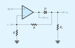
electronic_circuit_2.png
 
We have two cases here. \(\displaystyle v_I > 0\) and \(\displaystyle v_I < 0\).

When \(\displaystyle v_I > 0\), then \(\displaystyle v_A > 0\), and this gives a voltage across the diode, \(\displaystyle v_D \approx 0.7 \ \text{V}\).

In return because of the feedback, \(\displaystyle v_I = v_{-}\).

And from the circuit, we can see that \(\displaystyle v_O\) will have double the voltage of \(\displaystyle v_{-}\).

Or

\(\displaystyle v_{-} = \frac{R}{R + R}v_{O} = \frac{1}{2}v_{O}\)

The voltage across the diode is:

\(\displaystyle v_D = v_A - v_O = 0.7 \ \text{V}\)

\(\displaystyle \bold{(a)}\)

When \(\displaystyle v_I = 1 \ \text{V}\), then we have:

\(\displaystyle v_{-} = v_I = \textcolor{blue}{1 \ \text{V}}\)

\(\displaystyle v_O = 2v_{-} = 2(1) = \textcolor{blue}{2 \ \text{V}}\)

\(\displaystyle v_A = v_D + v_O = 0.7 + 2 = \textcolor{blue}{2.7 \ \text{V}}\)
 
\(\displaystyle \bold{(b)}\)

When \(\displaystyle v_I = 3 \ \text{V}\), then we have:

\(\displaystyle v_{-} = v_I = \textcolor{blue}{3 \ \text{V}}\)

\(\displaystyle v_O = 2v_{-} = 2(3) = \textcolor{blue}{6 \ \text{V}}\)

\(\displaystyle v_A = v_D + v_O = 0.7 + 6 = \textcolor{blue}{6.7 \ \text{V}}\)
 
Now when \(\displaystyle v_{I} < 0\), the diode will be removed from the circuit. It is like we have an open circuit. Therefore, no current will flow to the other side of the circuit. It means that:

\(\displaystyle v_O = 0\)

And since \(\displaystyle v_{-}\) depends on \(\displaystyle v_O\), it will be zero too. And \(\displaystyle v_A\) in this case will reach its minimum saturation level of \(\displaystyle -13 \ \text{V}\).

Then,

\(\displaystyle \bold{(c)}\)

When \(\displaystyle v_I = -1\), then we have

\(\displaystyle v_{-} = v_O = \textcolor{blue}{0}\)
\(\displaystyle v_A = \textcolor{blue}{-13 \ \text{V}}\)
 
We have already made our analysis for \(\displaystyle v_I < 0\).

Then,

\(\displaystyle \bold{(d)}\)

When \(\displaystyle v_I = -3 \ \text{V}\), we have:

\(\displaystyle v_{-} = v_O = \textcolor{blue}{0}\)
\(\displaystyle v_A = \textcolor{blue}{-13 \ \text{V}}\)
 
Also, find the average output voltage obtained when \(\displaystyle v_I\) is a symmetrical square wave of \(\displaystyle 1\)-\(\displaystyle \text{kHz}\) frequency, \(\displaystyle 5\)-\(\displaystyle \text{V}\) amplitude, and zero average.
Let \(\displaystyle V_o\) be the average output voltage.

\(\displaystyle V_o = \frac{\text{positive half-cycle} + \text{negative half-cycle}}{2} = \frac{v_{O+} + v_{O-}}{2}\)
 
When \(\displaystyle v_I = 5 \ \text{V}\), then

\(\displaystyle v_{O+} = 2v_{-} = 2(5) = 10 \ \text{V}\)

When \(\displaystyle v_I = -5 \ \text{V}\), then

\(\displaystyle v_{O-} = 0\)

Then,

\(\displaystyle V_o = \frac{10 + 0}{2} = 5 \ \text{V}\)
 
Top