solid shaft

logistic_guy

Senior Member
Joined
Apr 17, 2024
Messages
2,214
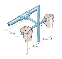
If the solid shaft \(\displaystyle AB\) to which the valve handle is attached is made of \(\displaystyle \text{C83400}\) red brass and has a diameter of \(\displaystyle 10 \ \text{mm}\), determine the maximum couple forces \(\displaystyle F\) that can be applied to the handle just before the material starts to fail. Take \(\displaystyle \tau_{\text{allow}} = 40 \ \text{MPa}\). What is the angle of twist of the handle? The shaft is fixed at \(\displaystyle A\).
solid_shaft.png
 
If you were an expert in beams and shafts like @khansaheb, you would instantly know that this problem is related to torsion. This means that we are dealing with shear stress.

Let me describe this problem in simple words. We are applying a torque on the shaft and an internal torque in the shaft is resisting our torque. We usually use \(\displaystyle \tau\) symbol to denote torque but here this symbol is reserved to shear stress, so let us call the internal torque \(\displaystyle T_{AB}\).

Therefore, we have this simple equation:

\(\displaystyle T_{AB} - 0.15F - 0.15F = 0\)

Since we have two unknowns, we have to think of something else to help us find one of them!

🤔🤔
 
Last edited:
.....Take τallow=40 MPa\displaystyle \tau_{\text{allow}} = 40 \ \text{MPa}τallow=40 MPa.
You have to use:
  1. Equation that co-relates the maximum value of elastic shear stress on the shaft and the applied torque
  2. Maximum value of shear stress (elastic) for the material.
This is a standard "worked-out example problem" in almost any freshman/sophomore level engineering mechanics text-book.
 
You have to use:
  1. Equation that co-relates the maximum value of elastic shear stress on the shaft and the applied torque
  2. Maximum value of shear stress (elastic) for the material.
There is a beautiful formula that relates the shear stress \(\displaystyle \tau\) to the internal torque \(\displaystyle T\).

\(\displaystyle \tau_{\text{allow}} = \frac{rT_{AB}}{J}\)

\(\displaystyle T_{AB} = \frac{J\tau_{\text{allow}}}{r}\)

Then, we have:

\(\displaystyle T_{AB} - 0.15F - 0.15F = 0\)


\(\displaystyle \frac{J\tau_{\text{allow}}}{r} - 0.15F - 0.15F = 0\)

We still have two unknowns, \(\displaystyle J\) and \(\displaystyle F\)!

😭😭
 
internal torque T\displaystyle TT.
That torque is the applied torque - which is in this case T whose magnitude is = 0.3 * F

J is the polar moment of inertia - a geometric property of the cross-section resisting the (externally applied) torque - similar to cross-sectional area resisting external force (creating tensile/compressive/shear stresses).
 
J is the polar moment of inertia
😱

You know that I am an expert in moments of inertia! How was I blind to realize that?

It is like a piece of cake to take a circular cross section of the shaft and calculate its moment of inertia.

\(\displaystyle J = \int r^2 \ dA = \int_{0}^{2\pi}\int_{0}^{r}r^3 \ dr \ d\theta = 2\pi \frac{r^4}{4} = \frac{\pi r^4}{2}\)
 
Last edited:
💚💙💜

\(\displaystyle \frac{J\tau_{\text{allow}}}{r} - 0.15F - 0.15F = 0\)


\(\displaystyle \frac{J\tau_{\text{allow}}}{r} - 0.3F = 0\)


\(\displaystyle \frac{\frac{\pi r^4}{2}\tau_{\text{allow}}}{r} - 0.3F = 0\)


\(\displaystyle \frac{\pi r^3\tau_{\text{allow}}}{2} - 0.3F = 0\)


\(\displaystyle \pi r^3\tau_{\text{allow}} - 0.6F = 0\)


\(\displaystyle F = \frac{\pi r^3\tau_{\text{allow}}}{0.6}\)

determine the maximum couple forces \(\displaystyle F\)
\(\displaystyle F = \frac{\pi (0.005)^3 40 \times 10^{6}}{0.6} = \textcolor{blue}{26.18 \ \text{N}}\)
 
What is the angle of twist of the handle?
The angle of twist is given by:

\(\displaystyle \phi = \frac{T_{AB}L}{JG} = \frac{0.3FL}{\frac{\pi r^4}{2}G}\)

\(\displaystyle \text{C83400}\textcolor{red}{\ \text{red brass}}\) \(\displaystyle \rightarrow 37 \ \text{GPa} \rightarrow\) shear modulus of elasticity

Plug in numbers.

\(\displaystyle \phi = \frac{0.3(26.18)0.15}{\frac{\pi(0.005)^4}{2}37 \times 10^{9}} = 0.032433 \ \text{rad} = \textcolor{blue}{1.86^{\circ}}\)
 
Top