electronic circuit

logistic_guy

Senior Member
Joined
Apr 17, 2024
Messages
2,214
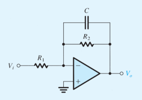
The figure shows a circuit that performs a low-pass STC function. Such a circuit is known as a first-order low-pass active filter. Derive the transfer function and show that the dc gain is \(\displaystyle \left(-\frac{R_2}{R_1}\right)\) and the \(\displaystyle 3\)-\(\displaystyle \text{dB}\) frequency \(\displaystyle \omega_{\tiny 0} = \frac{1}{CR_2}\). Design the circuit to obtain an input resistance of \(\displaystyle 10 \ \text{k}\Omega\), a dc gain of \(\displaystyle 40 \ \text{dB}\), and a \(\displaystyle 3\)-\(\displaystyle \text{dB}\) frequency of \(\displaystyle 1 \ \text{kHz}\). At what frequency does the magnitude of the transfer function reduce to unity?
electronic_circuit.png
 
The figure shows a circuit that performs a low-pass STC function. Such a circuit is known as a first-order low-pass active filter. Derive the transfer function and show that the dc gain is \(\displaystyle \left(-\frac{R_2}{R_1}\right)\) and the \(\displaystyle 3\)-\(\displaystyle \text{dB}\) frequency \(\displaystyle \omega_{\tiny 0} = \frac{1}{CR_2}\). Design the circuit to obtain an input resistance of \(\displaystyle 10 \ \text{k}\Omega\), a dc gain of \(\displaystyle 40 \ \text{dB}\), and a \(\displaystyle 3\)-\(\displaystyle \text{dB}\) frequency of \(\displaystyle 1 \ \text{kHz}\). At what frequency does the magnitude of the transfer function reduce to unity?

View attachment 39589

Please show us what you have tried and exactly where you are stuck.

Please follow the rules of posting in this forum, as enunciated at:


Please share your work/thoughts about this problem
 
The transfer function is defined as:

\(\displaystyle T(s) = \frac{V_{o}}{V_{i}}\)

I will take my node to be at the negative terminal. And by applying KCL, I get:

\(\displaystyle \frac{0 - V_{i}}{R_1} + \frac{0- V_{o}}{R_2 \ || \ \frac{1}{sC}} = 0\)

This gives:

\(\displaystyle \frac{V_{o}}{V_{i}} = -\frac{R_2 \ || \ \frac{1}{sC}}{R_1}\)

Let \(\displaystyle Z_R = R_2\) and \(\displaystyle Z_C = \frac{1}{sC}\).

\(\displaystyle Z = Z_R \ || \ Z_C = \left(\frac{1}{Z_R} + \frac{1}{Z_C}\right)^{-1} = \frac{Z_R Z_C}{Z_R + Z_C}\)

Derive the transfer function
\(\displaystyle T(s) = \frac{V_{o}}{V_{i}} = -\frac{Z}{R_1} = -\frac{1}{R_1}\frac{R_2\frac{1}{sC}}{R_2 + \frac{1}{sC}} = -\frac{1}{R_1}\frac{R_2}{sCR_2 + 1}\)

Or

\(\displaystyle T(j\omega) = \textcolor{blue}{-\frac{R_2/R_1}{j\omega CR_2 + 1}}\)
 
show that the dc gain is \(\displaystyle \left(-\frac{R_2}{R_1}\right)\)
The dc gain happens when \(\displaystyle \omega = 0\).

Then,

\(\displaystyle T(0) = -\frac{R_2/R_1}{j(0) CR_2 + 1} = \textcolor{blue}{-\frac{R_2}{R_1}}\)
 
show that the \(\displaystyle 3\)-\(\displaystyle \text{dB}\) frequency \(\displaystyle \omega_{\tiny 0} = \frac{1}{CR_2}\).
\(\displaystyle 3\)-\(\displaystyle \text{dB}\) frequency means \(\displaystyle |T(j\omega_0)| = \frac{R_2/R_1}{\sqrt{2}}\)

Then,

\(\displaystyle T(j\omega_0) = -\frac{R_2/R_1}{j\omega_0 CR_2 + 1}\)


\(\displaystyle |T(j\omega_0)| = \frac{R_2/R_1}{\sqrt{\omega_0^2 C^2R^2_2 + 1}} = \frac{R_2/R_1}{\sqrt{2}}\)


\(\displaystyle \frac{1}{\sqrt{\omega_0^2 C^2R^2_2 + 1}} = \frac{1}{\sqrt{2}}\)


\(\displaystyle \sqrt{\omega_0^2 C^2R^2_2 + 1} = \sqrt{2}\)


\(\displaystyle \omega_0^2 C^2R^2_2 + 1 = 2\)


\(\displaystyle \omega_0^2 C^2R^2_2 = 1\)


\(\displaystyle \omega_0^2 = \frac{1}{C^2R^2_2}\)


\(\displaystyle \omega_0 = \frac{1}{CR_2}\)
 
Design the circuit to obtain an input resistance of ..........
This part is a little bit challenging, and we will start it slowly but surely!

They have already given us the first piece of the puzzle.

\(\displaystyle R_1 = \textcolor{blue}{10 \ \text{k}\Omega}\)

We can use the given dc gain to find \(\displaystyle R_2\). The magnitude of the dc gain gives the linear gain which in turn gives us the relation between \(\displaystyle R_1\) and \(\displaystyle R_2\).

\(\displaystyle \left|-\frac{R_2}{R_1}\right| = 10^{\frac{\text{gain in dB}}{20}} = 10^{\frac{40}{20}}\)

\(\displaystyle \frac{R_2}{R_1} = 100\)

\(\displaystyle R_2 = 100 R_1 = 100(10000) = \textcolor{blue}{1 \ \text{M}\Omega}\)
 
Design the circuit to obtain .... and a \(\displaystyle 3\)-\(\displaystyle \text{dB}\) frequency of \(\displaystyle 1 \ \text{kHz}\).
We have already found the \(\displaystyle 3\)-\(\displaystyle \text{dB}\) angular frequency, \(\displaystyle \omega_{\tiny 0}\). That is:

\(\displaystyle \omega_{\tiny 0} = \frac{1}{CR_2}\)

Or

\(\displaystyle 2\pi f_{\tiny 0} = \frac{1}{CR_2}\)

Plug in values.

\(\displaystyle 2\pi(1000) = \frac{1}{C(1000000)}\)

This gives:

\(\displaystyle C = 1.59 \times 10^{-10} = \textcolor{blue}{159 \ \text{pF}}\)
 
At what frequency does the magnitude of the transfer function reduce to unity?
\(\displaystyle |T(j\omega)| = \frac{R_2/R_1}{\sqrt{\omega^2 C^2R^2_2 + 1}} = 1\)


\(\displaystyle \omega^2 C^2R^2_2 + 1 = R^2_2/R^2_1\)


\(\displaystyle \omega^2 = \frac{R^2_2/R^2_1 - 1}{C^2R^2_2}\)


\(\displaystyle \omega = \sqrt{\frac{R^2_2/R^2_1 - 1}{C^2R^2_2}}\)


\(\displaystyle 2\pi f = \sqrt{\frac{R^2_2/R^2_1 - 1}{C^2R^2_2}}\)


\(\displaystyle f = \frac{1}{2\pi}\sqrt{\frac{R^2_2/R^2_1 - 1}{C^2R^2_2}} = \frac{1}{2\pi}\sqrt{\frac{1000000^2/10000^2 - 1}{(159 \times 10^{-12})^2 1000000^2}} = \textcolor{blue}{100092 \ \text{Hz}}\)
 
Top